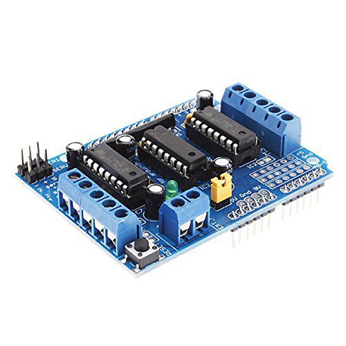
L293D motor control circuit
L293D motor control circuit is an expansion board for arduino boards, used to control all kinds of DC motors, stepper motors and servo motors. Arduino Motor Shield is designed neatly, beautifully and is fully compatible with Arduino boards: arduino uno r3, arduino leonardo, arduino mega2560, which can help you use and control easily and quickly.
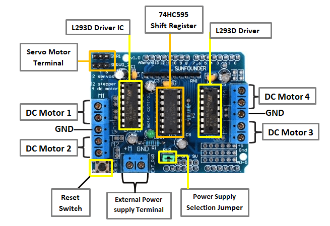
The Arduino Motor Shield uses 2 H L293D bridge ICs complete with protection modes and 1 logic 74HC595 logic IC to drive the motors.
L293D motor control circuit can control various types of motors such as step motor, servo motor, DC motor, with up to 36V voltage, maximum current of 600mA for each control channel.
SPECIFICATIONS:
- Input voltage: 4.5V to 36V.
- Compatible with Arduino Uno R3, Arduino Leonardo R3 and Arduino Mega 2560 boards.
- Can control DC motor (4 motors), servo motor (2 motors) and stepper motor (2 motors). 2 servo motor control ports are marked: Servo_1 and Servo_2 on the component. The DC motor control ports are marked as M1, M2, M, M4, respectively, the middle leg is GND.
- 2 servo motor control ports with 5V input voltage with high resolution timer, suitable for high precision Arduino control applications. Special no jitter.
- There are 2 IC Driver L293D, so there will be 4 H bridges to control 4 DC motors. Each H-bridge has a maximum output of 0.6A (maximum withstand current of 1.2A) in each control channel.
- The M ports use DC motor control which is controlled by a PWM signal.
- The driver also supports control of 2 stepper motors, with 2 ports for 2 servo motors that can be used for stepper motors. With Shield L293D, the stepper motor can operate in all modes: full step, half step and micro-step. The stepper motor used for drivers can be unipolar or bipolar.
- An RESET button is available to restart the Arduino board
Specifically, the number of motor control is as follows:
- 2 control jacks 2 RC servo motors.
- 4 control outputs to 4 independent DC motors.
- 2 step motor unipolar (unipolar) or bipolar (bipolar)
- Integrated resistance circuit connected to GND helps to not run automatically when starting the board.
The pins that Arduino Motor Shield uses are:
- Control pins 2 RC servo are connected to pins 9 and 10. Power supply is taken directly from the Arduino board.
- Motor 1 connected to pin 11
- Motor 2 connected to pin 3
- Motor 3 connected to pin 5
- Motor 4 connected to pin 6
- Pins 4, 7, 8, 12 use motor control through IC 74HC595
In addition to the convenience of using external power, on the Arduino Motor Shield use 1 PWR jumper purpose to get external power through the arduino board's DC jack to provide power for the motor to operate. If in the case we do not use this jumper, we must supply a separate power to the EXT_PWR pin to power the motor to operate.
Product same category
Categories
Youtube Channel
update
Facebook page
...
New product

LIÊN HỆ
GỞI THÔNG TIN ĐỂ NHẬN TƯ VẤN
Tài khoản giao dịch
Chủ tài khoản: Mr. Nhân
MBBank: 010419987979
(Chi nhánh Nha Trang, Khánh Hòa)
Tài khoản giao dịch
Chủ tài khoản: Mr. Thông
VietCombank: 0061001055299
(Chi nhánh Nha Trang, Khánh Hòa)MB Bank: 8000620012009
(Chi nhánh Nha Trang, Khánh Hòa)MẠNG XÃ HỘI
Chi nhánh Nha Trang
Số 21 Đường B4, KĐT VCN Phước Long, P.Phước Long, TP. Nha Trang, Khánh Hòa
0931.182.204
lkdientunhatrang@gmail.com
Chi nhánh Đà Lạt
75-77 Nguyễn Hoàng, Phường 7, TP Đà Lạt, Lâm Đồng
0972.879.983